MikroTik RouterBoard and MikroTik Wireless Router are popularly used now a days. MikroTik RouterBoard is used in ISP Network and MikroTik Wireless Router is specially used for home users. MikroTik RouterBoard requires custom configuration because it is used for large network. On the other hand, MikroTik Wireless Router is used in home for a small network.
MikroTik Wireless Router requires quick setup because home users are so hurry and not so technical. So, MikroTik RouterOS 7 provides a quick setup option. In this article, we are going to see the quick setup option of MikroTik RouterOS 7 using Winbox 4.
MikroTik Winbox 4
MikroTik Winbox 4 is a modern, simple and fast RouterOS 7 GUI. It is now available to download from MikroTik Software Download page for any OS platform. If you are yet not familiar with Winbox 4, download and install it in your OS and follow Quick Setup guide. We are using Winbox 4 for our quick setup guide.
MikroTik RouterOS 7 Quick Configuration
Connect the ISP cable to first ether port (ether1) and then connect a RJ45 cable to your PC and any other port of your MikroTik Router. Open Winbox 4 and select Neighbors from right panel of the login window.
The MAC of connected interface will be shown in Neighbors panel. Click on it and it will be assigned in Connect To input box of login panel.
Now put admin in Login input box and keep password field blank and then hit Connect button. You will now be able to login to MikroTik RouterOS 7.
Now follow the following steps to do quick setup of MikroTik RouterOS 7.
From Winbox 4, click on Quick Set menu item from left menu bar. Quick Set window will appear.
Choose Home AP from Quick Set dropdown menu. Home AP setup window looks like the following window.
MikroTik Home AP Quick Setup
Quick Wireless Setup
Click the Wireless panel and put an SSID (such as: MikroTik AP) in Network Name input box.
Click on WiFi Password Plus Sign (+) and put network password in the appeared input box.
Quick Internet Setup
ISP connection will be configured here. An ISP can provide three type connections – Automatic (DHCP), PPPoE or Static. Automatic has no extra configuration because everything will be assigned dynamically. PPPoE requires username and password and will be provided by your uplink ISP. Static connection requires IP Address, Subnet Mask and Default Gateway.
Click on Internet panel and choose your ISP connection type from Address Acquisition radio button.
For Automatic Connection
No need to do anything. Just select Automatic radio button and it will enable a DHCP client on ether1 port and connect to ISP DHCP Server.
For PPPoE Connection
Collect PPPoE Username, Password and PPPoE Service Name provided by ISP and put them accordingly and then click Reconnect button.
For Static Connection
Collect IP Address, Netmask and Gateway from ISP and put them accordingly. Also put DNS Server IP Address if your ISP provide you or you can use Google public DNS IP: 8.8.8.8 and 8.8.4.4.
Quick Local Network Setup
Click on Local Network panel and do the following steps.
Put LAN gateway IP address (such as: 192168.100.1) in IP Address input box.
Choose netmask from Netmask dropdown menu. For example: to get available 256 IP Addresses in Local network, choose 255.255.255.0(/24) option.
Click on Bridge All LAN Ports checkbox.
Click on DHCP Server checkbox.
Put DHCP Server IP address range (192.168.100.2-192.168.100.200) in DHCP Server Range input box.
Also click on NAT checkbox.
Now click Apply and OK button.
MikroTik RouterOS 7 Quick Setup
Your MikroTik Wireless Router is now ready. You can connect any device using wire or wireless, the device will get an IP address from LAN DHCP Server and can access internet connection.
MikroTik RouterOS 7 quick configuration using Winbox 4 has been discussed here. I hope, you will now be able to configure MikroTik RouterOS 7 using Winbox 4. However, if you face any confusion, feel free to discuss in comment or contact me from Contact page. I will try my best to stay with you.
MikroTik Wireless Router is one of the most popular and stable WiFi Routers. WiFi Zone for an ISP or for an office or for a home can easily be configured with MikroTik WiFi Router. MikroTik has a lot of WiFi Routers that can be used as a WiFi Access Point (AP), a WiFi Station or a WiFi Repeater. MikroTik Wireless Router can also be used as both WiFi Station and WiFi AP simultaneously. The simple usage of MikroTik Wireless Router is to create a WiFi Zone with MikroTik WiFi AP. So, in this article I will discuss how to configure MikroTik WiFi AP to create a WiFi Zone in a home or in an office or even in an ISP network using MikroTik hAP lite wireless router.
MikroTik WiFi Access Point
The bridge or ap-bridge mode of a MikroTik Wireless Router is used to create a WiFi Access Point. MikroTik Wireless Router offers creating meaningful SSID with WPA and WPA2 PSK security. MAC Address filtering can also be applied in MikroTik WiFi AP with Access List and RADIUS Server. A lot of WiFi Routers are available in MikroTik for different purpose. Among these we will configure a hAP lite (RB941-2nD) wireless router (but the configuration can be same for all MikroTik Wireless Routers) to create a WiFi Zone in a home, office or ISP.
Network Diagram
The following network diagram is being followed for this article configuration.
MikroTik WiFi Router
In this network diagram a hAP lite MikroTik Wireless Router is being used as a WiFi AP and LAN gateway. This wireless router has one WLAN interface and four Ethernet interfaces. WiFi AP will be created on WLAN interface so that wireless devices can be connected. Among four Ethernet interfaces, ether1 port will be used as WAN connection with IP network 192.168.70.0/30. We will create a bridge interface and configure a DHCP Server (with IP block 10.10.70.0/24) on this bridge interface and then add WLAN interface and ether2 to ether4 interfaces to this bridge so that WiFi users and LAN users can get IP address, default gateway and other network parameters from this DHCP Server automatically.
MikroTik WiFi AP Configuration
We will now configure WiFi AP and LAN gateway in MikroTik hAP light Wireless Router. Complete Wireless AP Setup and LAN Gateway Configuration can be divided into the following five steps.
Resetting Default RouterOS Configuration
WiFi AP Setup on WLAN Interface
Creating Bridge Interface and Adding LAN and WLAN Ports
Basic RouterOS Configuration
DHCP Configuration on Bridge Interface
Step 1: Resetting RouterOS Default Configuration
MikroTik Wireless RouterOS usually comes with default configuration. But default configuration sometimes makes you confused. So, I always suggest to reset and remove default configuration. The following steps will show how to reset and remove RouterOS default configuration.
Login to RouterOS using Winbox with admin user or any full permission user.
Click on System menu item and then click Reset Configuration option. Reset Configuration window will appear.
Click the No Default Configuration checkbox.
Click on Reset Configuration button. It will ask to confirm resetting configuration. Click Yes to confirm.
Now default configuration will be reset and Routerboard will be rebooted. After successful reboot, you will get a fresh and zero configuration RouterOS.
Resetting RouterOS Default Configuration
Step 2: WiFi AP Setup on WLAN Interface
MikroTik hAP lite wireless router has a WLAN interface where WiFi AP has to be setup. To setup WiFi Access Point in MikroTik Wireless Router we have to first create Security Profile and then create SSID to connect wireless devices.
Creating Security Profiles
To connect a wireless device with MikroTik WiFi AP, wireless devices must provide security key (password). MikroTik wireless supports both WPA PSK and WPA2 PSK authentication type. The following steps will show how to create passkey for MikroTik WiFi AP with Security Profile.
From Winbox, click on Wireless menu item. Wireless Tables window will appear.
Click on Security Profiles tab and then click on PLUS SIGN (+). New Security Profile window will appear.
Put a meaningful profile name (WiFi Profile) in Name input field.
Choose dynamic keys from Mode drop down menu.
Check WPA PSK and WPA2 PSK checkbox from Authentication Types panel.
Now provide strong password in WPA Pre-Shared Key and WPA2 Pre-Shared Key password box.
Click Apply and OK button.
MiKroTik Wireless AP Security Profile
Creating SSID for MikroTik WiFi AP
After creating Security Profile we will now set Wireless Mode and create SSID (Service Set Identifier) so that wireless devices can find our MikroTik Access Point with created SSID. The following steps will show how to create SSID and set wireless mode in hAP lite MikroTik Wireless Router.
Click on WiFi Interfaces tab and you will find WLAN interface (by default: wlan1) here. It may be disabled at first time. So, if you find disabled, click mouse right button on it and then click on Enable option to enable WiFi interface.
Double click on available and enabled WiFi Interface. Interface window will appear.
From General tab you can set WiFi interface name from Name input box or you can keep it default.
Click on Wireless tab and choose ap bridge from Mode dropdown menu.
Put SSID name (MikroTik AP) in SSID input box.
Now click on Advanced Mode button and choose your created security profile from Security Profile drop down menu.
Make sure Default Authenticate and Default Forward checkbox is checked. Otherwise devices will not be connected until MAC authentication.
Click Apply and OK button.
MikroTik WiFi AP Setup
Now created SSID will be found in wireless devices and wireless device can be connected providing password. You will find connected devices in Registration tab. But connection is not enough to get internet. IP address, default gateway and other network parameters have to provide to get internet to the connected devices. So, we will now do MikroTik Router basic configuration with creating bridge interface. We will also configure DHCP Server to assign IP address, default gateway and other network parameters automatically.
Step 3: Creating Bridge Interface and Adding LAN and WLAN Ports
We will now create a bridge interface and add ether2 to ether3 interfaces including WLAN interface to this bridge because we want to provide same block IP address to LAN and WiFi users. The following steps will show how to create bridge interface and add physical interfaces to it.
Click on Bridge menu item. Bridge interface will appear.
Click on Bridge tab and then click on PLUS SIGN (+). New Interface window will appear.
Put bridge interface name in (LAN_Bridge) Name input field.
Click Apply and OK button.
Now click on Ports tab and click on PLUS SIGN (+). New Bridge Port window will appear.
Choose ether2 interface from Interface dropdown menu.
Choose created bridge interface (LAN_Bridge) from Bridge dropdown menu.
Click Apply and OK button.
Similarly add ether3, ether4 and wlan1 interfaces to this bridge.
Adding Interface to Bridge
Step 4: Basic RouterOS Configuration
We will now do RouterOS basic configuration where we will assign WAN IP, LAN Gateway, DNS IP, and Default Gateway IP and configure NATing. The following steps will show how to do basic configuration in MikroTik Wireless Router.
Go to IP > Address menu item. Address List window will appear.
Click on PLUS SIGN (+). New Address window will appear. Put ISP provided IP address (192.168.70.2/30) in Address input box. Now choose ether1 from Interface dropdown menu. Click Apply and OK button.
Similarly, click on PLUS SIGN (+) again and put LAN Gateway IP (10.10.70.1/24) in Address input field and choose bridge interface (LAN_Bridge) from Interface dropdown menu and click Apply and OK button.
Now go to IP > DNS menu item. DNS Settings window will appear. Put your ISP provided DNS IP or Google Public DNS IP 8.8.8.8 in Servers input field.
Go to IP > Routes menu item. Route List window will appear. Click on Gateway input field and put ISP provided gateway IP (192.168.70.1) in this field. Click Apply and OK button.
Go to IP > Firewall menu item. Firewall window will appear. Click on NAT tab and then click on PLUS SIGN (+). New NAT Rule window will appear. From General tab choose srcnat from Chain drop down menu and put LAN Block (10.10.70.0/24) in Src. Address input field. Click on Action tab and choose masquerade from Action drop down menu and then click Apply and OK button.
Now click New Terminal menu item and ping google.com. If everything is OK, you will get response that means MikroTik Router is now ready to communicate to internet.
MikroTik Winbox Terminal
Step 5: DHCP Server Configuration on Bridge Interface
We will now setup DHCP Server on bridge interface so that WiFi users and LAN users can get IP address, default gateway and other network parameters automatically. The following steps will show how to setup DHCP Server on bridge interface in MikroTik RouterOS.
Go to IP > DHCP Server menu item. DHCP Server window will appear.
Click on DHCP Setup button. DHCP Setup window will appear.
Choose bridge interface (LAN_Bridge) from DHCP Server Interface drop down menu and then click Next button.
LAN Block (10.10.70.0/24) will be automatically assigned in DHCP Address Space input field. So, nothing to do. Just click Next button.
LAN Gateway (10.10.70.1) will automatically be assigned in Gateway for DHCP Network input field. So, just click Next button.
IP Pool from where IP address will be assigned to Wireless devices and LAN devices will be automatically assigned from LAN Block (10.10.70.2-10.10.70.254) in Addresses to Give Out input field. So, just click Next button.
Your assigned DNS Server IP will automatically be assigned in DNS Server input filed. So click Next button.
Default DHCP lease time is 10 minute. So, 10 minute will keep assigned in Lease Time input filed. If you want, you can increase lease time as much you want. Click Next button.
Now you will find DHCP Setup successful message window. Just click OK button.
MikroTik DHCP Server Setup
MikroTik WiFi AP with DHCP Server is now ready. Now connect any wireless device or connect any LAN device. The device will get IP address, default gateway and other network parameters automatically and be able to get internet access.
With this MikroTik WiFi AP configuration any wireless user who knows WiFi password can connect with SSID and any LAN user who will be connected with LAN cable can able to get access to DHCP Server and DHCP Server will be happy to provide him/her IP address, default gateway and other network parameters because there is no filter rule to block unauthorized access.
MikroTik Wireless or WiFi AP is smart enough granting access based on MAC address. But MAC address filtering can only save WiFi access. LAN users should also filter based on MAC Address. For this, it is always better to use Static DHCP Server Configuration which will filter access based on MAC Address.
How to Configure MikroTik WiFi AP with DHCP Server in hAP lite Wireless Router has been discussed in this article. I hope you will now be able to configure MikroTik Wireless Router following the above steps properly. However, if you face any confusion to follow the above steps properly, feel free to discuss in comment or contact with me from Contact page. I will try my best to stay with you.
Mikrotik devices are wonderful networking tools. They offer flexibility and cost empowerment to solve networking problems. But, the way we deploy Mikrotiks in the industry is creating multiple security risks. People are not spending the time to secure Mikrotik devices.
Organizations deploying Mikrotik devices are creating security risks inside their organization.
ISPs who are not tracking the Mikrotik deployments on their customers are creating a risk for their business, network, and other customers.
The Industry who are not pushing for better “out of the box” Mikrotic security is accepting massive DDoS attack, gateways for ransomware crews, and a range of other abuse.
It cannot be ignored that Mikrotik devices are 2022’s most dangerous malware platform. We hope this work will help engineers, administrators, and organizations seek out, secure, and clean up the Mikrotik devices in their network.
Step-by-Step Guide for Securing your Mikrotik Device
First, with any network device, there are core principles that lead to security and resiliency. These are general principles that we will point out in this guide. They are applied to any network vendor.
Second, we will present several deployment scenarios. In this scenario, we are working to secure a basic Mikrotik router connected to the Internet (see the figure).
Lastly, if you go through these steps and find problems, ASSUME YOUR ROUTER IS COMPROMISED! At the end of this process, you will need to do a NETINSTALL, rebuild the Mikrotik device, and start from scratch.
WHY?
The modern compromises to Mikrotik devices can get into the underlying Linux operating system. These RouterOS remediation steps cannot fix problems inserted into the device’s Linux. It must be rebuilt.
Step 0 – Assume your Mikrotik is infected, owned, and controlled by a Miscreant.
The number of exposed, vulnerable, and known Mikrotik devices is in the millions. Given this, it is best to assume that your device is controlled by a miscreant using your device for criminal activities. Criminal activities that put your network at risk.
Through this guide, we will continuously assume the Mikrotik device is compromised. Each step allows us to build confidence in the configuration and the deployment.
Assume miscreants already control your Mikrotik Devices.
Step 1 – Backup Your Device
Yes! The first step is to back up your Mikrotik device and copy the backup to a safe location. This action is common sense before making any changes to a device or the network.
Mikrotik’s new BACKUP documentation provides details. (https://help.mikrotik.com/docs/display/ROS/Backup)
Don’t depend on the Mikrotik Cloud Backup!
Since RouterOS v6.44 it is possible to securely store your device’s backup file on MikroTik’s Cloud servers; read more about this feature on the Mikrotik IP/Cloud page. But what happens if you cannot get to the cloud backup? It is common sense to have a local backup location along with the convenience of a cloud backup. Do both.
Step 2 – Upgrade Mikrotik’s Winbox
Ease of use is one of the core reasons why there are so many Mikrotiks deployed. People do not need to be network experts to get value. Mikrotik’s Winbox application is one of the key reasons. Winbox is a small utility that allows the administration of MikroTik RouterOS using a fast and simple GUI. It is a native Win32 binary but can be run on Linux and macOS (OSX) using Wine. All Winbox interface functions are as close as possible, mirroring the console functions, which is why there are no Winbox sections in the manual.
You now have confidence that you have the latest version of Winbox deployed on your network.
Step 3 – Upgrade RouterOS
Moving to an updated version of the RouterOS software is the first step. It is not a “security fix” but a critical security step.
Mikrotik’s Upgrading and Installation documentation provides details on how to upgrade. Upgrading to the latest stable version of Router OS software is recommended.
Step 4 – Username and Passwords
Mikrotik out-of-the-box has a default username of “admin” and NO PASSWORD! Yes, this contradicts the industry’s best common practices (BCPs). It exposes your brand new Mikrotik device to miscreants constantly scanning the Internet looking for new devices that have yet to change the default username and add a password. Mikrotik’s documentation has you connecting the device to the network with no security, then says ….
“Now anyone worldwide can access our router,so it is the best time to protect it from intruders and basic attacks.”
Just assume the miscreants have your Mikrotik username and password. Change your username and password!
Mikrotik’s Protecting the Router documentation has details to change the password. Here is a practical workflow:
Change the Password of the user “admin” on the device. Remember the new password.
Add new users to maintain the router. These new users would replace the “admin” user.
Test the new username and passwords to ensure you have access. Have a separate username/password for your Winbox access.
Test the Winbox configuration to ensure it works with the new usernames/passwords.
Delete the user “admin.”
Change the username and password to
Test your Passwords to see if compromised
The Have I been PWND site is a public service that allows people to check their usernames, emails, and passwords. Testing any new password on Have I been PWND is prudent, validating the exposure.
https://haveibeenpwned.com/
Use Have I Been PWNED as a tool to test your usernames and passwords!
Step 5 – Limit the Source IP Blocks to Connect to the Router
The world does not need to connect to your router. The world should not be telneting or trying to use Winbox from all over the world. Limit the IP Source address used for the username and the most critical services.
Restrict username access for the specific IP address. In this example, we’re using the network from the illustration 192.168.2.0/24
/user set 0 allowed-address=192.168.2.0/24
Restrict Winbox service access to be only from a specific subnet:
/ip service set winbox address=192.168.2.0/24
Step 6 – Change the port # for SSH
Changing the SSH port number is a trick to minimize brute-force password hacking on your router. Change and test the port before turning off the telnet service on the router!
The port number for SSH is 22 by default. Here, we change the default SSH port number from 22 to 2200. This will make it harder for miscreants’ “scanning tools” to find your SSH port and “brute force” password guessing.
/ip service set ssh port=2200
Test the SSH connection! Ensure you can SSH to the new port (2200 in this example).
Step 7 – Limit the Services Opened on the Router
Once you know SSH works on the new port, you can turn off the Telnet Service:
/ip service print
/ip service disable telnet
/ip service print
Don’t stop by turning off telnet. There is a range of services that Mikrotik turns on that are not needed.
The Best Common Practice (BCP) for security on network devices is to turn off everything! Then turn on specific functions/services as part of your network design. Minimize RISK by minimizing what is running in the background on your network device.
Start with disabling these services:
/ip service print
/ip service disable telnet,ftp,www,api,api-ssl
/ip service print
A bandwidth server is used to test throughput between two MikroTik routers. Disable it in the production environment. This can be used as a DDoS tool.
/tool bandwidth-server set enabled=no
Don’t let the router be a DNS DDoS Reflector. DNS cache might be configured on the router, which turns it into a DDoS Reflector. Make sure it it turned off.
/ip dns set allow-remote-requests=no
If you need the DNS Cache to have the router, explicitly set up the DNS function to restrict who can use the Mikrotik router for DNS traffic (i.e. only inside your network).
Step 8 – Turn off Direct Access via the MAC Address
By default, the mac server runs on all interfaces. That means anyone directly connected to the Mikrotik device can connect or telnet to the device. This allows miscreants inside the network to connect back to the device.
Mikrotik provides an up-to-date neighbor discovery service that includes the MNDP (MikroTik Neighbor Discovery Protocol), CDP (Cisco Discovery Protocol), and LLDP (Link Layer Discovery Protocol) in the Layer2 broadcast domain. It can be used to map out your network.
Miscreants, malware, and APT (advanced persistent threat actors) already inside your network can use Network Discover Protocol to map out your network.
The Best Common Practice (BCP) is to turn off Network Discovery by default.Mikrotik turns network discover ON by default. So it needs to be manually turned off:
To disable neighbor discovery on all interfaces:
/ip neighbor discovery-settings set discover-interface-list=none
Step 10 – Limit WHO on the Internet Can Access Your Mikrotik!
Limit which services can access the router on the Internet-facing “public interfaces” (see illustration). This is done with Mikrotik’s Firewall Service.
There are core access list/firewall filter principles for how you protect your router, network, services, and your organization. Protecting Routers, Switches, and Network Devices is a good video tutorial on YouTube that walks through these principles. In this example, IP connectivity on the public interface must be limited by the Mikrotik firewall feature. In this example, we will accept only ICMP(ping/traceroute), IP Winbox, and ssh access.
The is a mix of guidelines and references. Here are some to explore when building your firewall access rules to protect your router, network, and organization.
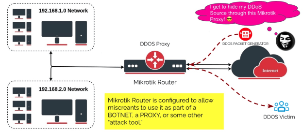
Step 11 – Don’t let your Mikrotik be used as a “DDoS Proxy!”
Mikrotik’s proxy, socks, UPnP, and other services are getting turned ON “accidentally,” turning the Mikrotik into a powerful DDoS Weapon. These features, combined with other Mikrotik capabilities, turn the device into a “bot” that becomes a member of the threat actor’s BOTNET.
DO NOT LET MISCREANTS USE YOUR MIKROTIK DEVICE FOR CRIMINAL ACTIVITY!
Mikrotik disables these by default. Check if they are turned on and manually turn them off – to be sure:
MikroTik caching proxy
/ip proxy set enabled=no
MikroTik socks proxy
/ip socks set enabled=no
MikroTik UPNP service
ip upnp set enabled=no
MikroTik dynamic name service or IP cloud
/ip cloud set ddns-enabled=no update-time=no
Step 12 – Start Cleaning Up Your “Compromised” Router
At this point, it is time to see if your Mikrotik device has been compromised. As you can see in this Mikrotik blog post – MĒRIS BOTNET – Mikrotik devices are sought after by threat actors and miscreants. As mentioned in the beginning, we are making the assumption your device has been compromised.
Check the Mikrotik Scheduler. The threat actor will install a rule that executes the script. Those scripts are evolving and creative. Check every scheduled script (under System → Scheduler). If you don’t know the script, download a copy, then delete it. Look for scripts with the fetch () method.
Check Files on the Mikrotik Router – Delete Unknown Files. Check the files on your Mikrotik. If you do not recognize it, download a copy, then delete the file.
Check the SOCKS Proxy. We covered this earlier, but it is worth checking again. An unknown SOCKS proxy server enabled on your router indicates that the router has been compromised.. You’ll find the setting under IP → SOCKS; if you do not use it, disable it;
Check for L2TP Clients. Threat Actors will use L2TP to control the router as part of a BOTNET. Look for any L2TP clients called lvpn, (or any other L2TP client unfamiliar to you). Delete these clients.
Check all the Firewall Rules! A threat actor will “open a hole” in the firewall to allow them to get remote access. For example, a firewall rule that allows remote access through port 5678 was used as part of the early versions of the MĒRIS botnet. Remove this rule, then check each firewall rule.
Trickbot is a modular trojan that’s been around since 2016 and is often used by cybercriminals to deliver ransomware or other malware. The miscreants using Trickbot have found they can use Mikrotik Routers as “proxies” to hide their Trickbot Command and Control.
The Trickbot “miscreant threat actors” are using the same approach we are working to prevent in the previous defensive steps:
Trickbot crews are using default MikroTik passwords where the device has been plugged in before being securely configured.
Trickbot crews scan for Mikrotik devices, then launch brute force “password guessing” attacks. Microsoft has seen attackers use some unique passwords that probably were harvested from other MikroTik devices.
Trickbot crews are exploiting CVE-2018-14847 on devices with RouterOS versions older than 6.42. This vulnerability gives the attacker the ability to read arbitrary files like user.dat, which contain passwords.
Microsoft’s Section 52 Team we able to explore Mikrotik confirmation commands to unravel the Trickbot crew’s source and intent. For example, we observed attackers issuing the following commands:
From the command, we can understand the following:
A new rule, similar to iptables, is created.
The rule redirects traffic from the device to a server
The redirected traffic is received from port 449 and redirected to port 80
The command looks like a legitimate network address translation (NAT) command that allows the NAT router to perform IP address rewriting. Here the Trickbot miscreants have compromised the Mikrotik router and configured the NAT for malicious activity. Trickbot’s Command and Control (C2C) is known for using ports 443 and 449.
How can you check if TrickBot’s Firewall Rule is installed?
Run the following command to detect if the NAT rule was applied to the device (completed by the tool as well):
/ip firewall nat print
If the following data exists; it might indicate a Trickbot infection:
Run the following command to remove the potentially malicious NAT rule:
/ip firewall nat remove numbers=
Step FINAL – NETINSTALL and Start from Scratch
The final step is the reality check. There is no way to RouterOS commands can fix malware inserted into the device’s Linux operating system. This process helps to shape your troubleshooting, confirm if there is a compromise, and the process to configure Mikrotik to be secure.
Netinstall is a tool for installing and reinstalling MikroTik devices running RouterOS. Always try using Netinstall if you suspect your device is not working properly.
Tools to Check your Mikrotik Device
Severial companies have tool to help you track, check, and secure your Mikrotik devices.
Shadowserver’s Daily Network Report
Shadowserver provides any organization with IP addresses, Autonomous System Numbers (ASNs), or Domain Names with daily report based on their vast array of security telemetry. The Daily Network Reports are FREE and a Public Service to protect the Internet. Mikrotik devices that are exposed, vulnerable, or compromised are listed in the reports. Find out more about the Network Reports and How to Subscribe to the reports on wwww.shadowserver.org.
Meris RouterOS Checker
The Meris RouterOS Checker is a open source tool crafted by Eclypsium to help network admins check their Mikrotik devices.
There is a Youtube Playlist for a “how to secure your Mikrotik” device here: Mikrotik Router Security – How to keep control over your Mikrotik devices. It is good to watch and listen to many of your peers working to secure their devices. Taking action to protect your network is the most critical element!
The materials and guides posted on www.senki.org here are designed to help organizations leverage the talent around them to get started with their security activities. Start with the Operator’s Security Toolkit and Meaningful Security Conversations with your Vendors. Each is no-nonsense security for all Operators. It provides details to help them build more security resilient networks. In the meantime, stay connected to the Senki Community to get updates on new empowerment and security insights.
MikroTik RouterOS is the stand-alone Linux operating system that is used with MikroTik’s networking equipment. However, that is not the only function it can perform. It is more than just an OS for routers. In fact, this software can even be installed on regular PCs to turn them into dedicated routers.
Nevertheless, the blog is a step-by-step tutorial on how to configure port forwarding in MikroTik. Before we get into it, however, we will first discuss a little more about the OS itself and give you a general idea of what port forwarding id&Mikrotik port Forwarding, and RouterOS Port Forwarding actually is.
What is Mikrotik?
MikroTik itself is a Latvian network equipment manufacturing company. They develop and sell wired and wireless network routers, network switches, access points, operating systems, and auxiliary software for their products.
MikroTik’s RouterOS is the operating system that powers its devices and has a very high level of flexibility when it comes to network management. RouterOS can also be installed on a PC turning it into a router with all the necessary features – routing, firewall, bandwidth management, wireless access point, backhaul link, hotspot gateway, VPN server, and more.
The feature that we will delve into today is RouterOS port forwarding. Unlike with other operating systems, the way to set it up might not be very intuitive, but not difficult at its core. Before setting up the configuration, let us first explain what port forwarding is.
What is Port forwarding?
Port forwarding is the process of intercepting data traffic headed for a computer’s IP/port combination and redirecting it to a different IP and/or port. This process can be easily done using a MikroTik router or any system running RouterOS.
Before we get to that, try to imagine the following situation:
You are an IT administrator. You created a large network, and someone wants to connect remotely to your VPS server or dedicated server to work remotely. You can’t share the server IP with that person for security reasons. What should you do? In this situation, you should use port forwarding on the MikroTik router to handle all the requests. Also, You can check out our Mikrotik VPS Server.
How to Configure Mikrotik Port Forwarding?
In this section, we’ll provide detailed step-by-step instructions for configuring MikroTik port forwarding for various purposes. We’ll cover three common scenarios: forwarding to an internal web server, FTP server, and SSH server. Each set of instructions will be presented clearly and concisely, catering to readers with varying levels of technical expertise.
Step 1: Log in to your own MikroTik server with admin privileges.
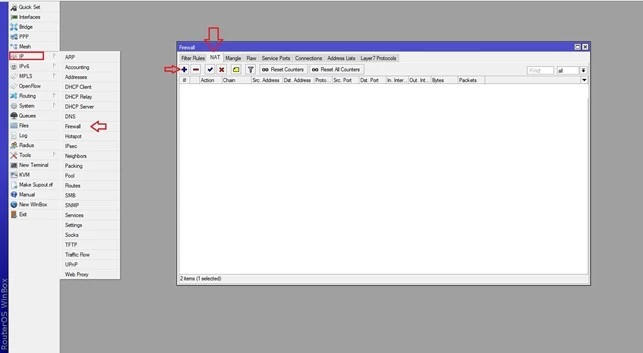
Step 2: Click on IP from the left side panel.
Step 3: In the newly opened submenu, click on Firewall.
Step 4: Head over to the NAT tab in the Firewall window.
Step 5: Click on the + button to create a new rule.
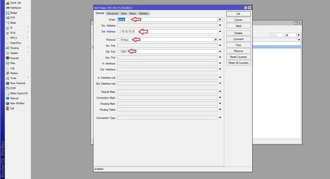
Note: In this scenario, assume the router connects to IP (10.10.10.10), and we want to forward all requests from (10.10.10.10:5847) to the (20.20.20.20:4324).
Step 6: Click on the General tab and select dstnat from the chain drop-down list.
Step 7: In the Dst. Address field, type the IP you wish to forward all requests from (i.e., 10.10.10.10 in our case).
Step 8: From the Protocol list, select the connection protocol, such as TCP.
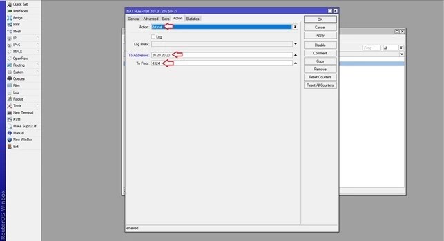
Step 9: In the Dst. Port field, type the port you wish to forward requests from (i.e., 5847 in this example). Step 10: Now, navigate to the Action tab.
Step 11: From the Action drop-down list, select dst-nat.
Step 12: In the To Addresses field, type the IP to which you wish to forward all requests (i.e., 20.20.20.20 in our case).
Step 13: In the To Ports field, type the port you want to forward requests to (i.e., 4324 in this example).
Step 14: Click on Apply and then on OK to save and add the new rule.
And that’s it. You have successfully configured your first port forwarding rule on MikroTik. To add new port forwarding rules, simply follow the steps with new ports or IPs.
Troubleshooting Tips
While configuring port forwarding is a valuable skill, issues may arise during the setup process. Here are some common problems users may encounter and tips on how to troubleshoot them:
Port Conflicts
Problem: Another device or application is already using the port you intend to forward.
Solution: Check for port conflicts by verifying that the chosen port is not in use elsewhere on your network. Consider changing the forwarded port if necessary.
Incorrect IP Address
Problem: Forwarding to the wrong internal IP address can lead to connection failures.
Solution: Double-check and ensure that you’ve entered the correct internal IP address of the target device or server in your port forwarding rule.
Firewall Blocking
Problem: The target server’s firewall may be blocking incoming traffic on the forwarded port.
Solution: Adjust the firewall settings on the target server to allow incoming connections on the forwarded port. Ensure both your router’s and server’s firewalls are correctly configured.
Dynamic IP Address
Problem: If your internal device has a dynamic IP address that changes, the port forwarding rule may become invalid.
Solution: Configure your router to assign a static or reserved IP address to the internal device. This ensures that the port forwarding rule remains effective even if the IP address changes.
ISP Restrictions
Problem: Some Internet Service Providers (ISPs) may impose restrictions on certain ports.
Solution: Contact your ISP to inquire about any port restrictions. Consider using alternative ports for forwarding if necessary.
Common Use Cases of Port Forwarding
Port forwarding is a versatile networking technique with a wide range of applications. Here, we’ll explore some common scenarios where port forwarding becomes a crucial tool:
Remote Desktop Access
In today’s interconnected world, the need for remote access to computers is paramount. Whether you’re an IT administrator managing servers or a remote worker accessing your office desktop, port forwarding enables secure access to remote desktops. By forwarding the appropriate port (e.g., TCP port 3389 for RDP) on your MikroTik router to the target computer’s IP, you can access it from anywhere, enhancing productivity and flexibility.
Online Gaming
Online gaming enthusiasts often rely on port forwarding to achieve optimal gaming experiences. Popular multiplayer games, like those on gaming consoles or PC platforms, require specific ports to be open for seamless connectivity. Port forwarding ensures that game traffic flows smoothly between players, reducing lag and enhancing the gaming experience.
Optimize your gameplay with a Gaming VPS Server! Deploy yours now and elevate your gaming experience with powerful resources. Explore the potential of Linux commands for ultimate customization and control.
Web Server Hosting
For businesses and individuals hosting websites or web applications, port forwarding is indispensable. By forwarding HTTP (port 80) or HTTPS (port 443) requests to a web server’s internal IP, you can make your website accessible to users on the internet. This is essential for businesses looking to establish an online presence and for developers testing their web applications.
File Sharing and FTP Servers
Sharing files across the internet or running an FTP server for file transfers often requires port forwarding. Whether you’re sharing files with colleagues, clients, or friends, port forwarding allows external users to connect to your FTP server securely. FTP typically uses port 21 for control connections and a range of ports for data transfers, making precise port forwarding crucial.
Surveillance Systems (NVR/DVR)
Security is a top concern for many homeowners and businesses. Network Video Recorders (NVRs) and Digital Video Recorders (DVRs) used for video surveillance can benefit from port forwarding. By forwarding specific ports, you can remotely access your surveillance system, view live camera feeds, and review recorded footage from anywhere with an internet connection.
Network Diagram
In this section, we’ll provide a visual representation of the network setup, which is essential for you to understand the context of the port forwarding configuration. This diagram illustrates how the MikroTik router is connected to both the WAN and LAN and how port forwarding plays a vital role in the overall network architecture.
The network setup consists of the MikroTik router with its ether1 interface connected to the WAN, having an IP address of 120.50.–.198. Meanwhile, the ether2 interface is connected to a LAN switch with an IP address of 193.168.20. Within the LAN, there are three servers: a web server, an FTP server, and an SSH server. These servers are only accessible to users within the local network. Port forwarding will enable users outside the local network to access these servers via the Internet.
Alternative Methods for Mikrotik Port Forwarding
While port forwarding is a widely used method for network configuration, there are alternative approaches and tools that can achieve similar results:
Virtual Private Networks (VPNs)
VPNs provide a secure and versatile way to access resources on your network remotely. By setting up a VPN server on your MikroTik router, you can create a secure tunnel for remote access to your local network, bypassing the need for port forwarding. VPNs are particularly useful for remote desktop access and ensuring data encryption.
Reverse Proxies
For web hosting purposes, reverse proxies can be an alternative to port forwarding. A reverse proxy server can receive incoming web requests and route them to the appropriate backend server, effectively hiding the internal server’s IP address. This method can enhance security and load balancing for web applications.
Cloud Services
Consider leveraging cloud-based solutions for certain applications. Cloud-hosted services, such as cloud-based surveillance systems or cloud-based web hosting platforms, eliminate the need for port forwarding by providing remote access through dedicated cloud infrastructure.
Notes and Recommendations
In this section, we present important considerations and recommendations to optimize your MikroTik port forwarding setup and safeguard against common pitfalls. By adhering to these guidelines, you can ensure a seamless and secure port forwarding configuration:
Keep RouterOS Updated
Before embarking on your port forwarding journey, it is imperative to verify that your MikroTik router is running the latest version of RouterOS. Regularly updating your router’s operating system ensures that you benefit from the latest features, bug fixes, and security enhancements. Visit the MikroTik website to download and install the most recent RouterOS release.
Firewall Configuration
To enable successful port forwarding, pay close attention to your server’s firewall settings. In addition to configuring port forwarding rules on your MikroTik router, you must permit incoming connections to the designated ports on the target server. Failing to adjust the server’s firewall may result in inaccessible services. Ensure that any firewall software or hardware on the server is properly configured to allow traffic on the forwarded ports.
Protocol and Port Accuracy
Precision is key when specifying the protocol and port numbers for your port forwarding rules. Be certain that you accurately identify the protocol type (e.g., TCP, UDP) and the port number associated with the service you intend to forward. Incorrect settings can lead to connectivity issues or security vulnerabilities. Consult the documentation of the service or application you are forwarding to verify the correct protocol and port details.
Logging and Monitoring
Implement logging and monitoring practices to keep track of port forwarding activities. MikroTik routers offer comprehensive logging capabilities that can assist in troubleshooting and security monitoring. Regularly review logs to detect any unusual or unauthorized access attempts. Consider setting up alerts or notifications for specific events, ensuring timely response to potential threats.
Security Best Practices
While port forwarding is a powerful tool for remote access, it should be approached with security in mind. Implement strong authentication mechanisms for services exposed through port forwarding. Utilize secure, complex passwords and, where applicable, consider implementing additional security layers such as VPNs or two-factor authentication (2FA). Regularly audit and update access credentials to maintain a high level of security.
Regular Testing
Periodically test the functionality of your port forwarding rules to verify that they are working as intended. Attempt remote access from outside your local network to confirm that the forwarded services are accessible. Regular testing helps identify and address any configuration issues or changes in network conditions.
Conclusion
We hope that with the help of this article, you now have a better understanding of Mikrotik port forwarding and can set up the port forwarding configuration on MikroTik without any issues. If you run into an issue or have any questions, you can post them in the comment section below or contact us via live chat or e-mail.
In modern cybersecurity, centralized log management is crucial for monitoring network activities and detecting potential threats. Wazuh, an open-source security platform, provides powerful log analysis and threat detection capabilities. By integrating pfSense, a widely used open-source firewall, with Wazuh via Syslog, administrators can enhance network visibility and security monitoring.
This guide will walk you through the process of configuring pfSense to send logs to Wazuh.
Configuring pfSense to Send Logs to Wazuh via Syslog
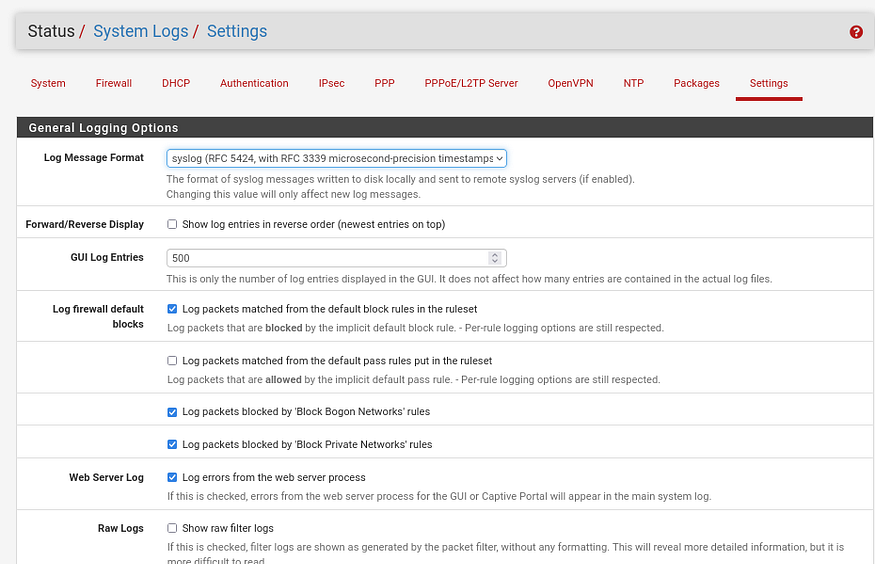
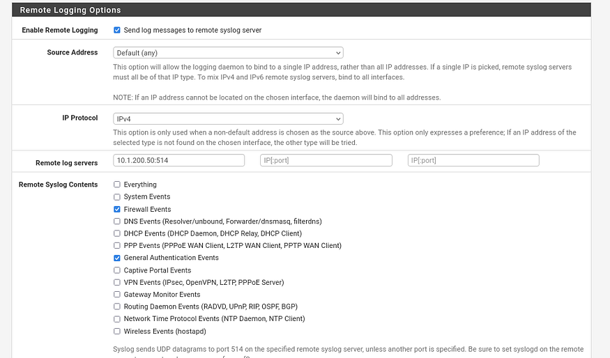
To enable remote logging in pfSense, navigate to Status → System Logs → Settings and scroll down to the Remote Logging Options section. Check Enable Remote Logging, then enter the IP address of your Wazuh server (e.g., 10.1.200.50) in the Remote Syslog Servers field. Set the Remote Syslog Port to 514, which is the default for Syslog. Next, select the log facilities you want to send, such as Firewall, System, and DHCP. For better compatibility with Wazuh,Don’t forget tp choose the RFC 5424 format. Finally, save the settings to apply the configuration.
Configuring Wazuh Server to Receive pfSense Logs
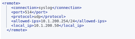
To configure Wazuh to receive logs from pfSense, edit the ossec.conf file on the Wazuh server. In the <remote> section, add the Syslog connection with port 514, using the UDP protocol, and set the allowed IP to the pfSense interface IP (e.g., 10.1.200.254). The local IP address of the Wazuh server should match the one set in the pfSense remote logging settings. After saving the changes, restart the Wazuh Manager and check the logs to confirm that pfSense logs are being received. If you see the logs, the setup is successful.
Testing Log Reception on Wazuh Manager with tcpdump
To verify that pfSense logs are reaching the Wazuh server, use tcpdump to capture Syslog traffic. Run tcpdump on the Wazuh server to listen for UDP packets on port 514, ensuring logs are being transmitted. If packets from the pfSense IP appear in the output, the connection is successful. Otherwise, check pfSense’s remote logging settings and firewall rules.
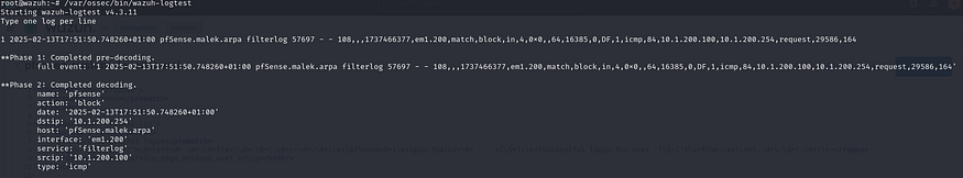
Example of a pfSense Log Received by Wazuh
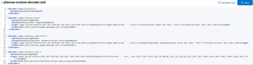
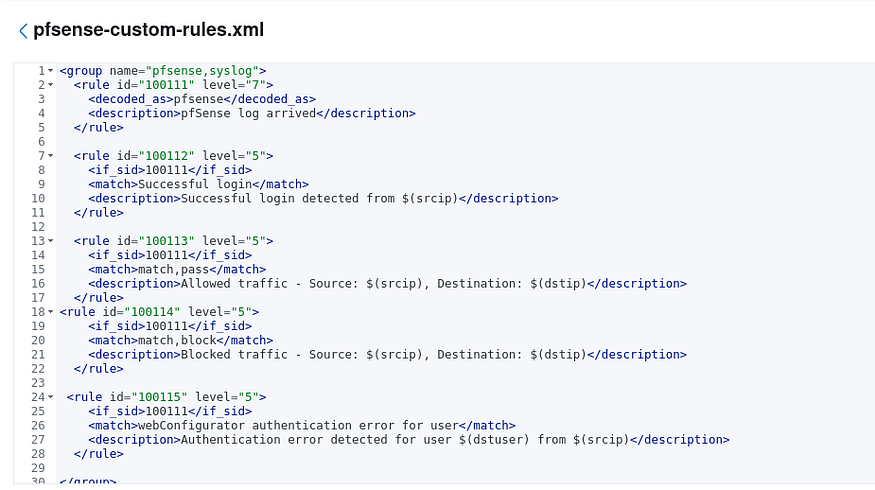
Creating a Decoder and Rules for Matching pfSense Logs in Wazuh
We created a decoder and rules in Wazuh to properly analyze and categorize pfSense logs. By default, Wazuh may not recognize pfSense logs correctly, as they have a specific format. The decoder helps extract important details like source IP, destination IP, and protocol from the raw logs. The rule then matches specific events, such as blocked traffic, and assigns them a severity level. This allows Wazuh to generate alerts for security-relevant events, making it easier to monitor and respond to potential threats in the network.
Testing a pfSense Log with a Custom Decoder in WazuhTesting a pfSense Log with a Custom Rule in Wazuh
pfSense Logs Successfully Integrated with Wazuh
Note: While it is possible to install the Wazuh agent directly on pfSense, it is not recommended due to compatibility and performance concerns. pfSense is a firewall appliance, and adding extra software like the Wazuh agent may affect its stability and security. Instead, using remote Syslog logging to send logs to a dedicated Wazuh server is the best practice for efficient monitoring without impacting pfSense’s performance.
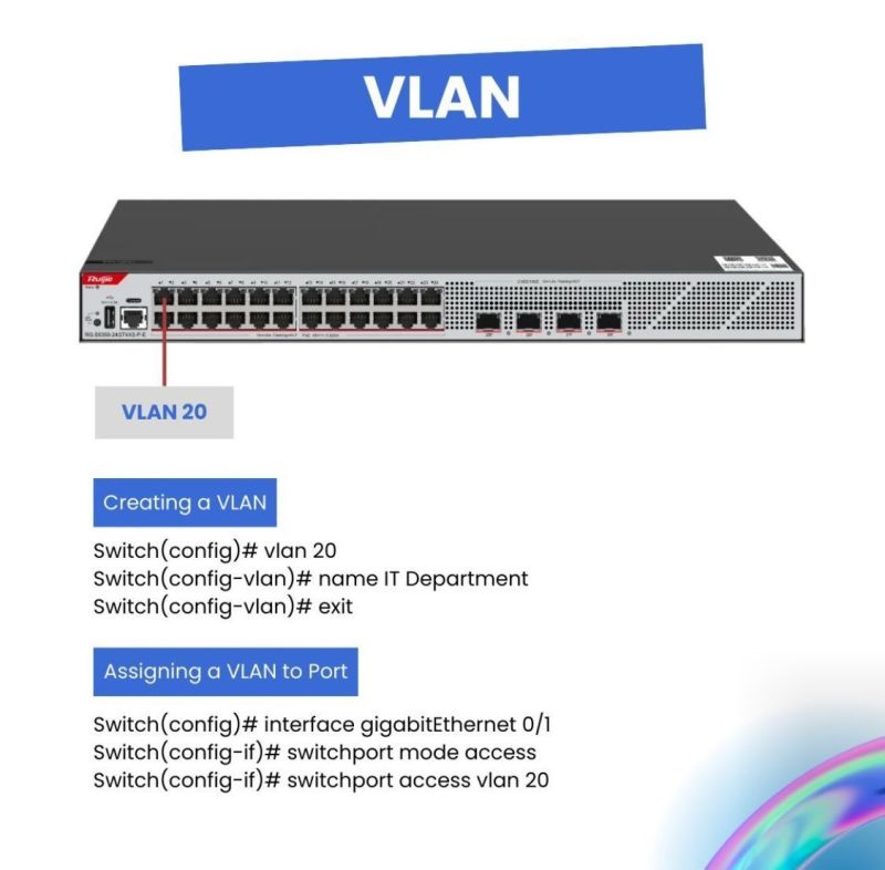
VLAN (𝑉𝑖𝑟𝑡𝑢𝑎𝑙 𝐿𝑜𝑐𝑎𝑙 𝐴𝑟𝑒𝑎 𝑁𝑒𝑡𝑤𝑜𝑟𝑘) is a basic networking technology that allows us to logically separate devices within a single physical network. Think of it as creating multiple virtual networks on one switch, giving you control over performance, security, and network management—all without the need for additional hardware.
𝐖𝐡𝐲 𝐬𝐡𝐨𝐮𝐥𝐝 𝐲𝐨𝐮 𝐜𝐚𝐫𝐞 𝐚𝐛𝐨𝐮𝐭 𝐕𝐋𝐀𝐍? In today’s fast-paced tech landscape, VLANs are essential for optimizing network performance and flexibility. Whether you’re in a business, educational institution, or a data center, VLANs provide benefits that can transform your network.
𝐇𝐞𝐫𝐞 𝐚𝐫𝐞 𝐭𝐡𝐞 𝐛𝐞𝐧𝐞𝐟𝐢𝐭𝐬 𝐨𝐟 𝐕𝐋𝐀𝐍: 1) Network Segmentation VLANs enable logical separation of devices based on functions, departments, or needs. For example, you can set up VLANs for Staff, IT department, and guests to ensure separation and better control.
ARP maps a Layer 3 IP address to an Unknown Layer 2 MAC address, which is key for Nic-to-Nic communication at the data link layer.
Here’s a quick overview:
1. PC1 needs PC3’s MAC and IP address to communicate. 2. The IP can be static or assigned dynamically via DHCP. 3. To test connectivity, John use PC1 to ping PC3 in the same LAN.
How it works: – PC1 sends an ARP request to resolve PC3’s MAC address. – The ARP request is broadcast, with unknown destination MAC set to all F’s. – PC3 replies with its MAC address with an ARP reply, allowing PC1 to send the ICMP request to eventually get an ICMP reply from PC3.
Understanding ARP is key to knowing how data moves through a network for effective communication and to troubleshoot various issues.
This article will guide you through building a Streamlit chat application that uses a local LLM, specifically the Llama 3.1 8b model from Meta, integrated via the Ollama library.
Prerequisites
Before we dive into the code, make sure you have the following installed:
Python
Streamlit
Ollama
Setting Up Ollama and Downloading Llama 3.1 8b
First, you’ll need to install Ollama and download the Llama 3.1 8b model. Open your command line interface and execute the following commands:
# Install Ollama
pip install ollama

# Download Llama 3.1 8b model
ollama run llama3.1:8b
Creating the Modelfile
To create a custom model that integrates seamlessly with your Streamlit app, follow these steps:
In your project directory, create a file named Modelfile without any extension.
Open Modelfile in a text editor and add the following content:
model: llama3.1:8b
This file instructs Ollama to use the Llama 3.1 8b model.
The code
Importing Libraries and Setting Up Logging
import streamlit as st
from llama_index.core.llms import ChatMessage
import logging
import time
from llama_index.llms.ollama import Ollama

logging.basicConfig(level=logging.INFO)
streamlit as st: This imports Streamlit, a library for creating interactive web applications.
ChatMessage and Ollama: These are imported from the llama_index library to handle chat messages and interact with the Llama model.
logging: This is used to log information, warnings, and errors, which helps in debugging and tracking the application’s behavior.
time: This library is used to measure the time taken to generate responses.
Initializing Chat History
if 'messages' not in st.session_state:
    st.session_state.messages = []
st.session_state: This is a Streamlit feature that allows you to store variables across different runs of the app. Here, it’s used to store the chat history.
The if statement checks if ‘messages’ is already in session_state. If not, it initializes it as an empty list.
Function to Stream Chat Response
def stream_chat(model, messages):
    try:
        llm = Ollama(model=model, request_timeout=120.0)
        resp = llm.stream_chat(messages)
        response = ""
        response_placeholder = st.empty()
        for r in resp:
            response += r.delta
            response_placeholder.write(response)
        logging.info(f"Model: {model}, Messages: {messages}, Response: {response}")
        return response
    except Exception as e:
        logging.error(f"Error during streaming: {str(e)}")
        raise e
stream_chat: This function handles the interaction with the Llama model.
Ollama(model=model, request_timeout=120.0): Initializes the Llama model with a specified timeout.
llm.stream_chat(messages): Streams chat responses from the model.
response_placeholder = st.empty(): Creates a placeholder in the Streamlit app to dynamically update the response.
The for loop appends each part of the response to the final response string and updates the placeholder.
logging.info logs the model, messages, and response.
The except block catches and logs any errors that occur during the streaming process.
Main Function
def main(): st.title("Chat with LLMs Models") logging.info("App started")
model = st.sidebar.selectbox("Choose a model", ["mymodel", "llama3.1 8b", "phi3", "mistral"]) logging.info(f"Model selected: {model}")
except Exception as e: st.session_state.messages.append({"role": "assistant", "content": str(e)}) st.error("An error occurred while generating the response.") logging.error(f"Error: {str(e)}")
if __name__ == "__main__": main()
main: This is the main function that sets up and runs the Streamlit app.
st.title("Chat with LLMs Models"): Sets the title of the app.
model = st.sidebar.selectbox("Choose a model", ["mymodel", "llama3.1 8b", "phi3", "mistral"]): Creates a dropdown menu in the sidebar for model selection.
if prompt := st.chat_input("Your question"): Takes user input and appends it to the chat history.
The for loop displays each message in the chat history.
The if statement checks if the last message is not from the assistant. If true, it generates a response from the model.
with st.spinner("Writing..."): Shows a spinner while the response is being generated.
messages = [ChatMessage(role=msg["role"], content=msg["content"]) for msg in st.session_state.messages]: Prepares the messages for the Llama model.
response_message = stream_chat(model, messages): Calls the stream_chat function to get the model’s response.
duration = time.time() - start_time: Calculates the time taken to generate the response.
response_message_with_duration = f"{response_message}\n\nDuration: {duration:.2f} seconds": Appends the duration to the response message.
st.session_state.messages.append({"role": "assistant", "content": response_message_with_duration}): Adds the assistant’s response to the chat history.
st.write(f"Duration: {duration:.2f} seconds"): Displays the duration of the response generation.
The except block handles errors during the response generation and displays an error message.
To run your Streamlit app, execute the following command in your project directory:
streamlit run app.py
Make sure your Ollama instance is running in the background to get any activity or results.
“Llama 3.1 8b generating a detailed response to the question ‘What are Large Language Models?’ in the Streamlit app.”“Continuation of the conversation, showing the final part of the Llama 3.1 8b’s response about Large Language Models.”
Training Models with Ollama
The same steps can be utilized to train models on different datasets using Ollama. Here’s how you can manage and train models with Ollama.
“Interactive chat interface with Llama 3.1 8b in the Streamlit app, showcasing real-time response generation.”
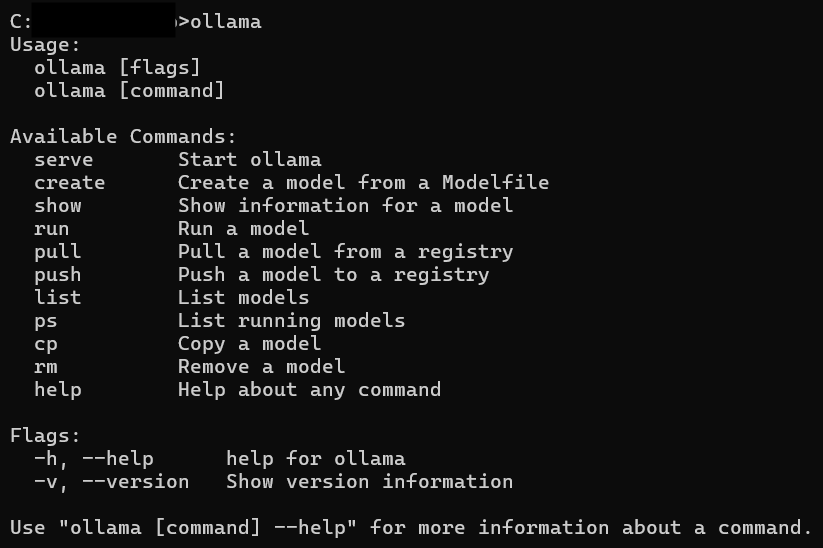
Ollama Commands
To use Ollama for model management and training, you’ll need to be familiar with the following commands:
Example: Creating and Using a Model
Create a Modelfile: Create a Modelfile in your project directory with instructions for your custom model.
Content of Modelfile:
# Example content for creating a custom model
name: custom_model
base_model: llama3.1
data_path: /path/to/your/dataset
epochs: 10
3. Create the Model: Use the create command to create a model from the Modelfile.
ollama create -f Modelfile
4.Run the Model: Once the model is created, you can run it using:
ollama run custom_model
Integrate with Streamlit or whatever: You can integrate this custom model with your Streamlit application similarly to how you integrated the pre-trained models.
By following these steps, you can create a Streamlit application that interacts with local LLMs using the Ollama library.
C:\your\path\location>ollama
Usage:
 ollama [flags]
 ollama [command]
Available Commands:
 serve Start ollama
 create Create a model from a Modelfile
 show Show information for a model
 run Run a model
 pull Pull a model from a registry
 push Push a model to a registry
 list List models
 ps List running models
 cp Copy a model
 rm Remove a model
 help Help about any command
Flags:
 -h, - help help for ollama
 -v, - version Show version information
Use "ollama [command] - help" for more information about a command.
Additionally, you can use the same steps and Ollama commands to train and manage models on different datasets. This flexibility allows you to leverage custom-trained models in your Streamlit applications, providing a more tailored and interactive user experience.
Implementation with Flask
This methodology can also be utilized to implement chat applications using Flask. Here is an outline for integrating Ollama with a Flask app:
Flask Application Setup
Install Flask:
pip install Flask
2. Create a Flask App:
from flask import Flask, request, jsonify from llama_index.core.llms import ChatMessage from llama_index.llms.ollama import Ollama import logging
@app.route('/chat', methods=['POST']) def chat(): data = request.json messages = data.get('messages', []) model = data.get('model', 'llama3.1 8b')
try: llm = Ollama(model=model, request_timeout=120.0) resp = llm.stream_chat(messages) response = "" for r in resp: response += r.delta logging.info(f"Model: {model}, Messages: {messages}, Response: {response}") return jsonify({'response': response}) except Exception as e: logging.error(f"Error during streaming: {str(e)}") return jsonify({'error': str(e)}), 500
if __name__ == '__main__': app.run(debug=True)
Running the Flask Application
Save the code in a file (e.g., app.py) and run the following command:
python app.py
This will start the Flask application, and you can make POST requests to the /chat endpoint with JSON data containing the messages and model to get responses from the Llama model.
Integrating Flask with Ollama
By following similar steps as shown for Streamlit, you can integrate Ollama with a Flask application. The stream_chat function can be reused, and the Flask routes can handle the interaction with the model, making it easy to create scalable chat applications.
Conclusion
By following this guide, you’ve successfully set up a Streamlit chat application using a local LLM. This setup allows you to interact with powerful language models directly from your local machine, providing a visually appealing and interactive experience. Whether you’re asking general questions or delving into specific inquiries, your app is now equipped to handle it all.
https://cdn.embedly.com/widgets/media.html?src=https%3A%2F%2Fgiphy.com%2Fembed%2FXXMWSAMXq1ebfxcKdV%2Ftwitter%2Fiframe&display_name=Giphy&url=https%3A%2F%2Fmedia.giphy.com%2Fmedia%2Fv1.Y2lkPTc5MGI3NjExOXozaW8xb2N2M2M2MTQ2Z3BjcjhvZDJhcHdscno0cmd1enVxbndxdiZlcD12MV9naWZzX3NlYXJjaCZjdD1n%2FXXMWSAMXq1ebfxcKdV%2Fgiphy.gif&image=https%3A%2F%2Fmedia1.giphy.com%2Fmedia%2Fv1.Y2lkPTc5MGI3NjExODBvM2wxdjhyNHRud2FsOTJ3M2tyaDUwYnlmaGExNzV5OGFnaGtvOCZlcD12MV9pbnRlcm5hbF9naWZfYnlfaWQmY3Q9Zw%2FXXMWSAMXq1ebfxcKdV%2Fgiphy.gif&key=a19fcc184b9711e1b4764040d3dc5c07&type=text%2Fhtml&schema=giphy“Thank you for exploring the power of Large Language Models with us. Goodbye!”
Before knowing what is active directory, answer this question, what is directory??
What is Directory?
Directory basically means a hierarchical arrangement of different kind of entities. Entities can be anything like document, books, access controls, address book or dictionary.
What is Active directory?
Active directory is like a digital directory made for computers and other devices to be managed in a network. Active Directory (AD) is a Microsoft technology which is a primary feature of windows server and Operating system (OS). AD enables centralized management, authentication, authorization and access control mechanisms.
Why making directories are important?
Making directories is like arranging your space properly along with proper rights and access mechanisms.
Directories are important because it helps in:
Organizing the information or documents. It keeps digital directories stored in a logical manner along with easy access.
Directories makes our work efficient and quicker.
Security measures like access controls and authentication and authorization becomes easy to embed in well-organized directories.
Scalability increases. Scalability means ease of adding new data or files into the directory.
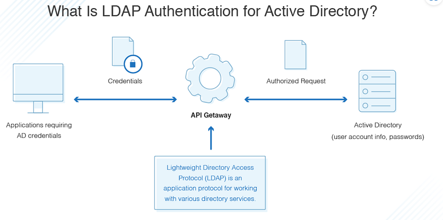
Directories allows ease integration between systems and applications. Protocols like LDAP (Lightweight Directory Access Protocol) {we will see what is that in some time} & APIs {Application Programming Interface} enables interoperability between software platforms, allowing them to exchange information
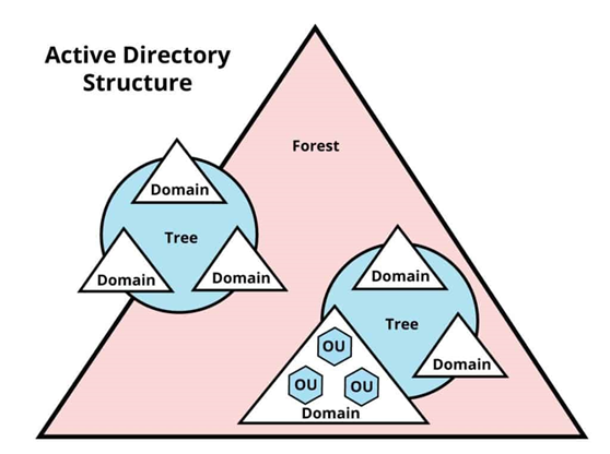
Architecture of Active Directory
As we saw above, that Active directory is a hierarchical structure made for efficient usage and organization of entities.
Active directory consists of different components. Some of the major components are:
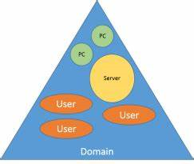
1. Domains: This is the fundamental unit of whole logical organization. It represents a group of network objects (computers, users, devices) that share a common directory database, security policies, and trust relationships. Each domain has its own unique name and can be managed independently.
2. Domain Controllers (DCs): These are the servers that store a copy of AD Database & authenticate users & computers within the domain. They sync with the changes which happens in AD database at the same time to ensure consistency and fault tolerance.
3. Active Directory Database: This is the huge database which contains every information like objects, users, groups, computers, Ous etc along with different schemas and structures.
4. Tree & child domains: Think this as a family tree, which we used to make in pre-primary sections. It is the hierarchical structure starting from the main node to child nodes.
5. Forest: It is the collection of more than 1 trees/domains which share a common schema, configuration and global catalog.
6. Organizational Units (OUs): These are like the class CR’s. They manage and handle objects within a specific assigned domain. They add group policies, assign admin tasks, simplify directory management etc.
7. Global Catalog (GC): This is responsible for having partial replica of all the objects from each domain within the forest. Think of this like you are a student and you are searching for relevant course in a specific college. Then you will see the global catalogue and select a specific course.
Services of Active Directory
AD DS — Active directory Domain Services — These are the core services provided by Microsoft Windows OS. It has different features but basically its responsible for organizing and controlling access to network resources in Windows domain environment.
Basic services provided by AD DS are:
Authentication: It means verification of the identity of user or device. Example entering the password for account login.
Authorization: It means level of authority or level of access control. Example you are allowed to use lab computers in school but you aren’t allowed to use teacher’s side computer from the staff room.
Directory Services: This is a store room which stores and organizes information about users, groups, computers and other network resources in centralized database.
Certificate service: It keeps an eye on managing, revoking and issues related to the certificates used for authentication, encryption and digital signatures.
DNS Integration: AD DS facilitates the service of DNS (name resolution services). It converts the IP address into domain name and vice versa.
Some Key protocols associated with AD DS are:
1. LDAP (Lightweight Directory Access Protocol): This protocol is easy to understand and implement. It allows clients to search, add, modify, and delete directory objects like users, groups, computers etc. It works over TCP/IP and it is the primary means of communication between ADDS clients and domain controllers.
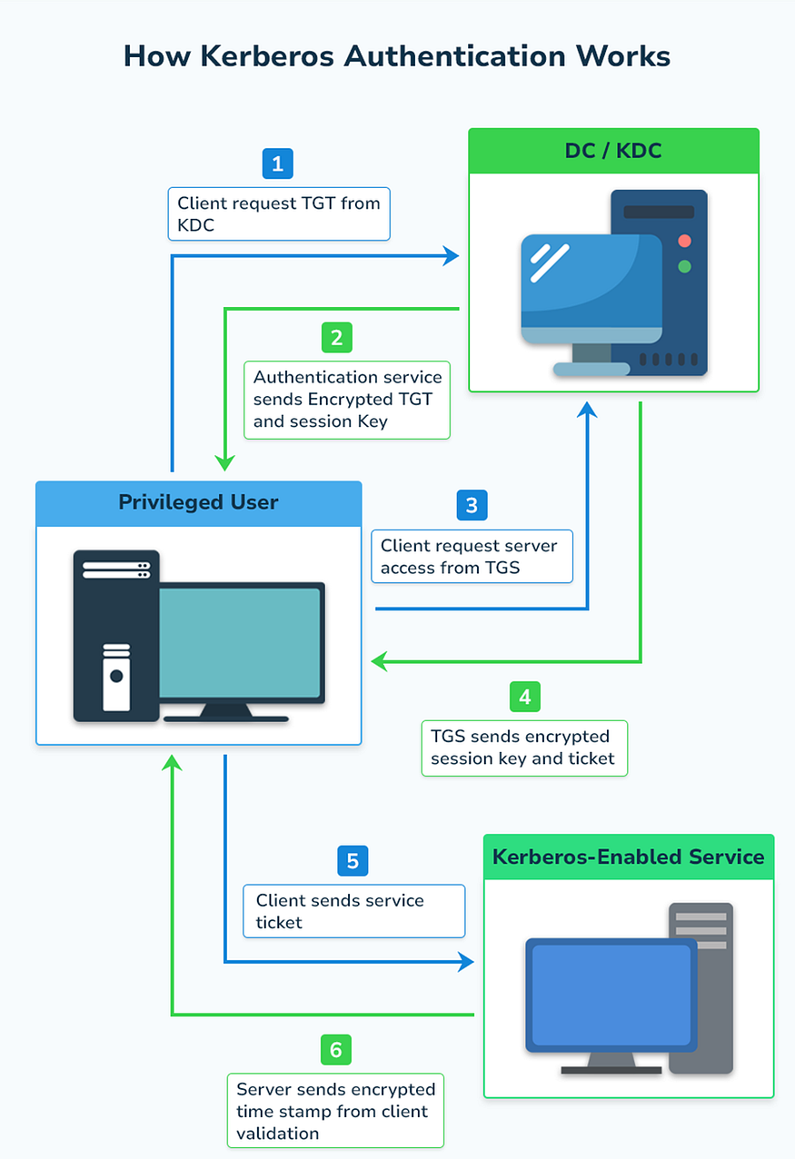
2. Kerberos Authentication: As the name speaks, it is used for secure authentication between clients and domain controllers (DCs). It works over TCP & UDP. The main components of Kerberos are Authentication Server, Database and TGS (Ticket Granting Server).
Process of Kerberos:
a. User sends log in request (ticket-granting request). This request is sent to KDC (Key Distribution center).
b. Authentication server uses the verification method for user using database. If the user gets verified then he/she gets the ticket-granting-ticket (TGT) and session key. If not, then the log in request fails. TGT and session key are encrypted using user’s password.
c. Then comes the role of TGS that is Ticket Granting server. TGS verifies the TGT and issues a service ticket for requested service. The service ticket is encrypted using the service’s secret key, not the user’s password.
d. The target service then decrypts the service ticket using its own secret key and verifies the user’s identity. If the verification is successful, the user is granted access to requested service.
3. NTLM (New Technology LAN Manager): It is used as single sign on processes (SSO). When a user tries to access a network, server sends a challenge (16-byte random numbers), which is a random string of characters. User encrypts the challenge using a hash of user’s password and sends it back to server. Server sends this to DC and DC retrieves the user’s password from the database and encrypts the challenge. Then DC compares the encrypted challenge & client response. If both matches then authentication is successful and access is granted.
5. Kerberos & LDAP over SSL/TLS: LDAPS & Kerberos authentication over SSL/TLS becomes more secure which increases the confidentiality and integrity for directory operations.
Advantages Of AD:
Centralized Management — Managing everything under a single domain is known as centralized management. AD manages users, computers, groups & other networks centrally.
Single Sign-On — Users can log in to different applications or resources using a single domain credentials.
Integration with Microsoft services — AD is integrated with different Microsoft services like Exchange Server, SharePoint & office 365 which increases productivity.
Group policy management — AD gives the right to enforce policies and configurations in the specific part of network or devices. This enhances security management.
Identity Management — AD allows admins to manage user identities, credentials & access permissions.
Disadvantages Of AD:
Complexity — Implementing and managing AD & AD Domain Services (ADDS) is complex and requires proper in-depth understanding.
Single point of failure- If the main primary domain controller fails then whole directory and services can crash down.
Maintenance Overhead — ADDS requires more efforts to maintain starting from software updates to patching vulnerabilities to uphold performance.
Compatibility — AD is specifically made for windows but if you want to add it in another operating system then it might become challenging.
Cost — AD requires licensing fees and may require additional hardware resources which increases the cost.